4 minutes
Study of Bridge Rectifier
Aim
The aim of this study is to understand the working of a bridge rectifier and to observe its input and output waveforms.
Components Required
| Component | Quantity |
|---|---|
| Diode | 4 |
| Resistor | 4 |
| Capacitor | 1 |
| Transformer | 1 |
Equipments Needed
- Digital multimeter
- Function generator
- Oscilloscope
- Connecting wires
Theory
- A bridge rectifier is an electronic circuit that converts an alternating current (AC) input into a direct current (DC) output.
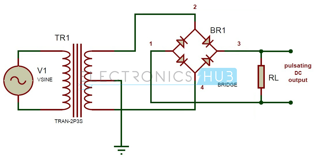
- The rectifier circuit consists of four diodes arranged in a bridge configuration. The AC input is applied to the diagonals of the bridge, and the DC output is taken from the center of the bridge.
- During the positive half cycle of the AC input, diodes D1 and D2 conduct and provide a positive output.
- During the negative half cycle of the AC input, diodes D3 and D4 conduct and provide a negative output.
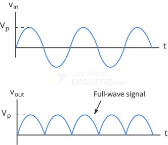
- The DC output is a pulsed signal, which can be smoothed using a filter capacitor to obtain a pure DC signal.
- The bridge rectifier is a simple, efficient, and cost-effective solution for converting AC to DC.
- The bridge rectifier circuit is commonly used in power supplies, chargers, and other applications where a DC output is required. T The bridge rectifier is a versatile circuit that can be used in many applications, making it an important component in the field of electronics.
Advantages
- The main advantage of a bridge rectifier over a half-wave rectifier is that it utilizes both positive and negative cycles of the AC input, resulting in a higher efficiency and a more regulated DC output.
- The use of four diodes provides full-wave rectification, which results in a higher DC output compared to a half-wave rectifier.
- The bridge rectifier circuit can also be used to isolate the DC output from the AC input, providing electrical isolation and protection to the load.
During Positive Half-Cycle 👇🏻
During Negative Half-Cycle 👇🏻
Procedure
Assemble the circuit of a bridge rectifier using the components listed above.
Connect the digital multimeter to measure the voltage and current levels.
Connect the function generator to the AC input of the rectifier and the oscilloscope to the DC output.
Set the function generator to produce a sinusoidal waveform of desired frequency and amplitude.
Turn on the oscilloscope and adjust its settings to observe the input and output waveforms.
Observe the voltage and current levels using the digital multimeter.
Vary the frequency and amplitude of the input waveform and observe the changes in the output waveform.
Repeat the above steps for different values of load resistance.
Plot the input and output waveforms on a graph paper.
Calculate the rectification efficiency of the circuit.
Observe the effect of adding a filter capacitor on the output waveform.
Vary the value of the filter capacitor and observe the changes in the output waveform.
Plot the effect of the filter capacitor on the output waveform.
Study the effect of load resistance on the output waveform.
Calculate the peak inverse voltage (PIV) of the circuit.
Study the effect of PIV on the diodes.
Observe the effect of reverse biasing the diodes.
Study the effect of using different types of diodes on the output waveform.
Observe the effect of using different values of resistors on the output waveform.
Plot the effect of all the above parameters on the output waveform.
Circuit Diagram
Input and Output Waveforms
Precautions
- Use diodes with a high PIV rating to prevent damage.
- Use a filter capacitor with a suitable value to reduce the ripples in the output waveform.
- Use a transformer with a high voltage rating to prevent damage.
- Connect the diodes in the correct polarity to avoid damage.
- Use a load resistance with a suitable value to avoid overloading the circuit.
- Observe proper safety measures when working with high voltage and current levels.
- Avoid short circuits in the circuit.
- Avoid reverse biasing the diodes.
- Use a function generator with a stable output to obtain accurate results.
- Use an oscilloscope with a high input impedance to avoid loading the circuit.
- Observe proper grounding techniques to avoid any electrical shock.
- Avoid touching the circuit components when power is applied.
- Avoid exposing the circuit to moisture or high temperature.
- Regularly check the circuit components for any signs of damage.
- Store the circuit components in a safe and dry place when not in use.
Summary
In this study, we learned about the working of a bridge rectifier and observed its input and output waveforms. We also studied the effect of various parameters such as frequency, amplitude, load resistance, filter capacitor, PIV, and diodes on the output waveform.
Conclusion
The bridge rectifier is a useful device for converting AC input into a DC output. With proper design and use of components, it can provide a regulated DC output with reduced ripples. The study of a bridge rectifier helps in understanding the principles of rectification and filtering in electronics.
803 Words
2023-01-28 19:03