9 minutes
Study of HWR and FWR Using CT Transformer
Part-1: Study of Half-Wave Rectifier
Aim
To study the half-wave rectifier and its input and output waveform.
Components Required
| Component | Quantity |
|---|---|
| Diode | 1 |
| Resistor | 1 |
| Capacitor | 1 |
| Transformer | 1 |
| Power Supply | 1 |
Equipment Required
- Oscilloscope
- Function Generator
- Breadboard
- Connecting Wires
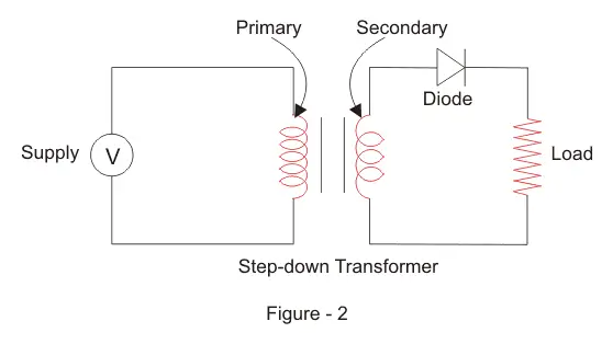
Circuit Diagram 👇🏻
Theory
- The half-wave rectifier is a simple circuit that converts AC voltage into a pulsating DC voltage. It consists of a diode that is connected in series with the load resistor and an AC source. The diode only allows current to flow in one direction, i.e., from the anode to cathode.
- During the positive half-cycle of the AC voltage, the diode is forward-biased, and it conducts current. This results in the flow of current through the load resistor and the production of a positive voltage across it.
- During the negative half-cycle of the AC voltage, the diode is reverse-biased, and it does not conduct current. This results in the absence of current flow through the load resistor and the production of a zero voltage across it.
The output of the half-wave rectifier is a pulsating DC voltage that has a lower DC component compared to the full-wave rectifier. The pulsating DC voltage can be smoothened using a filter circuit, such as a capacitor filter, to obtain a nearly constant DC voltage. The efficiency of the half-wave rectifier is lower compared to the full-wave rectifier due to the absence of current flow during the negative half-cycle of the AC voltage.
In practical applications, the half-wave rectifier is used in low-power applications where the requirement of DC voltage is low, and the efficiency is not a major concern. For example, it can be used in battery chargers, small power supplies, and voltage regulators.
Advantages
In addition, the half-wave rectifier is easy to construct, and it requires fewer components compared to the full-wave rectifier. This makes it a cost-effective solution for low-power applications. Moreover, the output voltage waveform of the half-wave rectifier is easier to analyze compared to the full-wave rectifier, making it a good choice for educational purposes.
The major disadvantage of the half-wave rectifier is its low efficiency. As only half of the AC cycle is utilized to produce DC voltage, the power loss is significant. The output voltage waveform also contains a large amount of ripples, which makes it unsuitable for high-precision applications.
Another limitation of the half-wave rectifier is its output voltage waveform. The output voltage waveform contains a large number of ripples, which can cause noise in sensitive circuits. Additionally, the output voltage is not constant, and it changes with the variations in the AC input voltage. This makes it unsuitable for applications where a constant DC voltage is required.
Conclusion
- In conclusion, the half-wave rectifier is a simple and cost-effective solution for low-power applications. However, it is not suitable for applications where high efficiency, constant DC voltage, and low ripple are required.
Procedure
Assemble the circuit components as per the circuit diagram.
Connect the AC input voltage to the primary winding of the transformer.
Connect the secondary winding of the transformer to the diode.
Connect the load resistor to the cathode of the diode.
Connect the positive terminal of the power supply to the anode of the diode and the negative terminal to the cathode of the diode.
Turn on the power supply and set the voltage to the required level.
Observe the waveform at the output of the diode using an oscilloscope.
Record the DC component and the ripple voltage in the output waveform.
Repeat the steps for different input AC voltages and load resistances.
Plot the waveforms and analyze the output for different conditions.
Observe the change in output voltage and ripple voltage for different input AC voltages and load resistances.
Repeat the steps for different values of load resistors and capacitors.
Observe the effect of adding a smoothing capacitor on the output waveform.
Verify the results with the theoretical values and conclude the experiment.
Input and Output Waveforms 👇🏻
Precautions
- Handle circuit components with care.
- Ensure that the power supply voltage is
WITHINthe rated range. - Connect the wires and components properly to avoid short circuits.
- Take care of the
POLARITYwhile connecting the diode. - Use a suitable fuse to protect the circuit from damage due to overloading.
- Be cautious while making adjustments to the circuit to avoid any damage.
- Always use insulated tools while working with the circuit.
- Wear protective gear, such as gloves and safety glasses, while handling the circuit components.
- Use a multimeter to verify the circuit connections and waveform outputs.
- Take proper precautions while handling the high voltage AC input.
Summary
The study of half-wave rectifier and full-wave rectifier using a center-tapped transformer is an important topic in the field of electronics. These rectifiers convert the AC input voltage into a pulsating DC output voltage. The half-wave rectifier produces a unidirectional voltage output with a lower DC component compared to the full-wave rectifier. On the other hand, the full-wave rectifier produces a higher DC component in the output voltage and is more efficient than the half-wave rectifier.
Conclusion
In conclusion, the half-wave and full-wave rectifiers are important components in power electronics. They are widely used in applications such as power supplies, battery chargers, and inverters. Understanding their working principle and practical implementation is crucial for engineers and students in the field of electronics. The study of rectifiers provides a foundation for exploring advanced topics such as power electronics, AC-DC conversion, and voltage regulation.
Part-2: Study of Full Wave Rectifier Using Center Tapped Transformer
Aim
The aim of this experiment is to study the working of a full-wave rectifier using a center-tapped transformer and to observe the output waveform.
Components Required
The following components are required to perform this experiment:
| Component | Description |
|---|---|
| Center-tapped transformer | A center-tapped transformer is used to step-down the incoming AC voltage. |
| Diodes | Diodes are used to convert AC voltage into a unidirectional DC voltage. |
| Resistor | A resistor is used to load the rectifier circuit. |
Equipments Required
The following equipments are required to perform this experiment:
- Oscilloscope
- Power supply
- Connecting wires
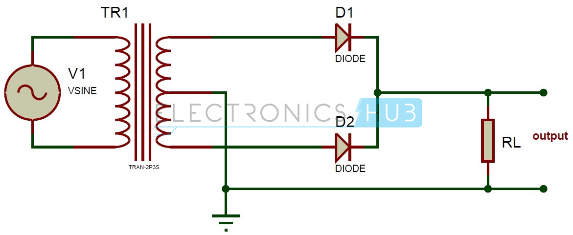
Circuit Diagram 👇🏻
Theory
A full-wave rectifier is an electronic circuit that converts an AC input voltage into a unidirectional DC voltage. It is composed of diodes that allow the current to flow in only one direction, which is from the anode to the cathode. The center-tapped transformer is used to derive two equal and opposite polarities from the AC source. The two half-cycles of the AC voltage are fed to the diodes and the resulting output is a continuous DC voltage.
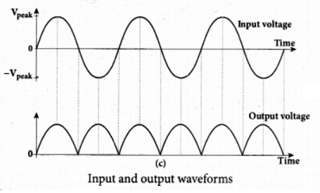
In a full-wave rectifier, both positive and negative half-cycles of the AC voltage are utilized. During the positive half-cycle of the AC voltage, the diode connected to the positive half of the secondary winding of the transformer conducts and the diode connected to the negative half remains non-conducting. During the negative half-cycle, the situation is reversed. This results in a continuous DC voltage output, which is the average value of the AC voltage.
During Positive Half-Cycle 👇🏻
During Negative Half-Cycle 👇🏻
Advantages
- The full-wave rectifier provides several advantages over the half-wave rectifier. The first advantage is that the output waveform is much smoother and more constant compared to the half-wave rectifier. This makes the full-wave rectifier more suitable for applications where a steady DC voltage is required, such as charging batteries, powering DC motors, and regulating voltage.
- Another advantage of the full-wave rectifier is that it has a higher efficiency compared to the half-wave rectifier. The full-wave rectifier utilizes both the positive and negative half-cycles of the AC voltage, whereas the half-wave rectifier only uses one half-cycle. This results in a higher average output voltage, which leads to a higher efficiency.
- Additionally, the full-wave rectifier has a lower ripple voltage compared to the half-wave rectifier. The ripple voltage is the alternating voltage that is present in the DC output voltage. A lower ripple voltage means that the output voltage is smoother and more stable, which is important in applications where a steady voltage is required.
Conclusion
In conclusion, the full-wave rectifier provides a more stable, efficient, and steady DC voltage compared to the half-wave rectifier. It is the preferred choice for applications where a constant DC voltage is required.
Procedure
Connect the input AC voltage source to the center tapped transformer.
Connect the output of the center tapped transformer to the diode bridge rectifier circuit.
Connect the output of the diode bridge to the load resistance.
Connect the oscilloscope to the output of the load resistance and to the input AC voltage source.
Switch on the input AC voltage source.
Adjust the oscilloscope to observe the input AC voltage and the output rectified voltage.
Note down the voltage readings for different values of load resistance.
Repeat the above steps for different values of input AC voltage.
Plot the input AC voltage and output rectified voltage waveform for each load resistance.
Analyze the effect of changing load resistance on the rectified output voltage.
Analyze the effect of changing input AC voltage on the rectified output voltage.
Study the ripple factor and peak inverse voltage of the full wave rectifier circuit.
Draw the conclusion based on the observed results.
Input and Output Waveforms
Precautions
- Handle circuit components with care.
- Ensure that the power supply voltage is within the rated range.
- Connect the wires and components properly to avoid short circuits.
- Take care of the polarity while connecting the diodes.
- Use a suitable fuse to protect the circuit from damage due to overloading.
- Be cautious while making adjustments to the circuit to avoid any damage.
- Ensure that the transformer is properly grounded.
- Always use insulated tools while working with the circuit.
- Wear protective gear, such as gloves and safety glasses, while handling the circuit components.
- Use a multimeter to verify the circuit connections and waveform outputs.
Summary
In this experiment, the full wave rectifier using center tapped transformer was studied. The input AC voltage was applied to the center tapped transformer, and the output of the center tapped transformer was fed to the diode bridge rectifier circuit. The effect of changing load resistance and input AC voltage on the rectified output voltage was analyzed. The ripple factor and peak inverse voltage of the full wave rectifier circuit were also studied.
Conclusion
The full wave rectifier using center tapped transformer is an important circuit used in power supplies. The experiment was performed to study the effect of changing load resistance and input AC voltage on the rectified output voltage. The ripple factor and peak inverse voltage of the full wave rectifier circuit were also studied. The results obtained in this experiment provide a clear understanding of the full wave rectifier circuit and its behavior under different conditions.
1781 Words
2023-01-28 19:08