3 minutes
Study of Resistors
Study Of Resistors
Basic Resistor
Diagram: A basic resistor.
Part 1: Study of Resistors
Working of Resistor
Aim
The aim of this section is to provide a comprehensive understanding of resistors, their components, equipments, and types.
Components List
- Resistor
- Multimeter
Equipments
- Power Supply
- Breadboard
Types Of Resistors
- Fixed Resistors
- Variable Resistors
Information about Fixed Resistors
Fixed resistors are electrical components that have a fixed value of resistance, meaning that their resistance does not change. This type of resistor is commonly used to limit the current flow in a circuit and to divide voltage.
Information about different types of Fixed Resistors
- Carbon Film Resistor: These resistors are made by depositing a thin layer of carbon on a cylindrical ceramic or plastic form. They are the most common type of fixed resistor and offer a low cost solution with a relatively high resistance tolerance.
- Metal Film Resistor: These resistors are made by depositing a thin layer of metal on a cylindrical ceramic or plastic form. They offer improved resistance tolerance compared to carbon film resistors and are more stable.
- Wire Wound Resistor: These resistors are made by winding a wire, typically made of nickel-chromium alloy, around a cylindrical form. They offer high power handling capabilities and precise resistance values, making them suitable for use in high-power applications.
Resistor Colour Coding
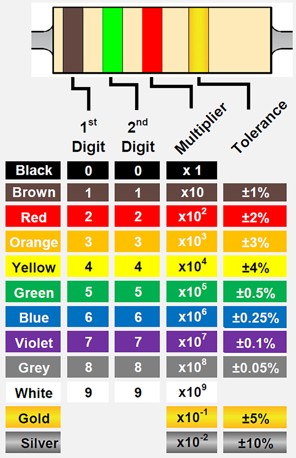
Resistor Colour Coding
Information about Variable Resistors
Variable resistors, also known as potentiometers, allow the resistance value to be adjusted. They are commonly used in applications where the resistance value needs to be changed, such as volume control in a stereo system.
Information about different types of Variable Resistors
- Potentiometer: A potentiometer is a three-terminal resistor where the resistance between two terminals can be adjusted using a sliding contact known as a wiper.
- Rheostat: A rheostat is a two-terminal resistor where the resistance can be adjusted using a sliding contact. Rheostats are typically used to control the current flow in a circuit.
Part 2: Potential divider arrangement
Aim
The aim of this section is to study the potential divider arrangement in detail and understand its applications in electronics.
Components List
- Resistor
- Voltage Source
Equipments
- Breadboard
- Multimeter
Theory
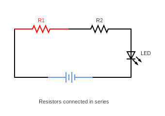
In a potential divider arrangement, two resistors are connected in series to a voltage source. The voltage across each resistor is proportional to its resistance, with the voltage across the first resistor (R1) being Vout and the voltage across the second resistor (R2) being (Vin - Vout). By knowing the voltage across the resistors, the resistance values can be calculated using Ohm’s law, which states that the current in a circuit is equal to the voltage divided by the resistance.
Diagram
Formula for potential divider arrangement
Vout = (R2/(R1 + R2)) * Vin
Example
Given Vin = 10V and R1 = 2kΩ and R2 = 4kΩ, find Vout.
Vout = (R2/(R1 + R2)) * Vin Vout = (4kΩ/(2kΩ + 4kΩ)) * 10V Vout = (4kΩ/6kΩ) * 10V Vout = (2/3) * 10V Vout = 6.67V
For Notes, and practical images, refer this:
Conclusion
In this study, we have covered the basics of resistors, including their components, types, and the potential divider arrangement. Understanding resistors and their behavior is crucial in many electrical and electronics applications.
530 Words
2023-01-28 23:43