4 minutes
Testing of Diodes and Transistors
Aim
The aim of this study is to understand the methods of testing diodes and transistors and to identify the working and faulty components.
Components Required
| Component | Description |
|---|---|
| Diodes | Any standard diode |
| Transistors | Any NPN or PNP transistor |
| Resistor | Any value between 1kΩ to 10kΩ |
| Multimeter | Digital multimeter with diode and transistor testing function |
Equipments Needed
- Breadboard
- Jumper Wires
Theory
Definition of Diode
A diode is a two-terminal electronic component that allows current to flow in one direction only (forward direction) and blocks it in the reverse direction. It acts like a one-way valve for current in a circuit.
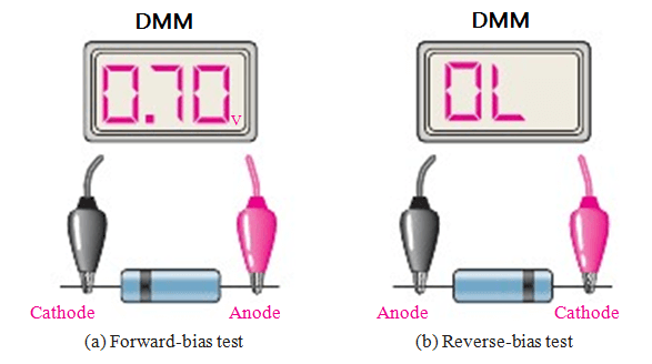
Forward Bias: When the Anode of diode is connected to positive of supply and the cathode is connected to the negative of the supple, it is said to be in forward bias.
Reverse Bias: When the Anode is connected to negative of supply and the cathode is connected to positive of supply it is said to be in reverse bias.
Diode Testing
- A diode is a two-terminal electronic component that allows current to flow in only one direction.
- The basic principle behind the functioning of a diode is based on the difference in the concentration of electrons in the p-type and n-type semiconductor material.
- The p-type material has a shortage of electrons and the n-type material has an excess of electrons.
- When a voltage is applied to the diode, it creates a potential difference between the p-type and n-type material, resulting in the flow of electrons from the n-type material to the p-type material.
- In the case of a diode, the multimeter measures the forward and reverse resistance of the diode to determine its working status. The forward resistance of a diode should be low, while the reverse resistance should be infinite.
Example Of Diode Test
Transistor Testing
- A transistor is a three-terminal electronic component that can be used as a switch or amplifier.
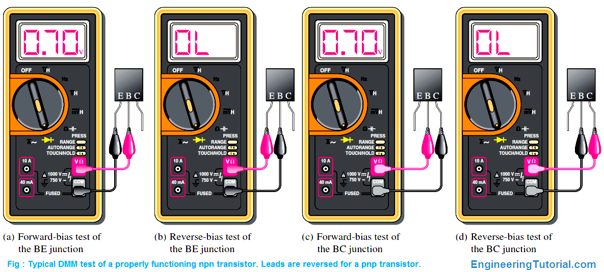
- The most common type of transistor is the bipolar junction transistor (BJT), which has two p-n junctions.
- The base-emitter junction is forward-biased, and the base-collector junction is reverse-biased.
- In the switching operation, the base current controls the flow of collector current, allowing the transistor to act as an on-off switch.
- In the amplification operation, the transistor amplifies the input signal applied to the base and produces a corresponding output signal at the collector.
- In the case of a transistor, the multimeter measures the current gain of the transistor, which is defined as the ratio of collector current to base current. The current gain of a transistor should be high, typically in the range of 100 to 1000.
Example Of Transistor Test
- The testing of diodes and transistors is important in the design and maintenance of electronic circuits.
- A digital multimeter is a versatile tool that can be used to test both diodes and transistors.
- The procedure for testing diodes and transistors involves setting up the circuit on a breadboard, connecting the multimeter, and measuring the forward and reverse resistance of the diode and the current gain of the transistor.
- It is important to observe proper wiring and connectivity in the circuit and to set the multimeter to the correct testing mode before measuring.
- Additionally, it is important to use a suitable diode and transistor for testing and to avoid exposing the circuit to high temperature or moisture.
Conclusion
- In conclusion, the testing of diodes and transistors is an important step in the design and maintenance of electronic circuits. By understanding the basic principles and procedures of testing, we can ensure the proper functioning of the components and improve the reliability of the circuit.
Procedure
Connect the diode to the breadboard as per the circuit diagram.
Set the multimeter to diode testing mode.
Measure the forward and reverse resistance of the diode.
Compare the measured values with the standard values to determine the working status of the diode.
Repeat the same steps for the transistor, but set the multimeter to transistor testing mode.
Measure the current gain of the transistor.
Compare the measured values with the standard values to determine the working status of the transistor.
Precautions
- Use a suitable diode and transistor for testing.
- Observe proper wiring and connectivity in the circuit.
- Set the multimeter to the correct testing mode before measuring.
- Avoid exposing the circuit to high temperature or moisture.
- Use appropriate protective gear while handling the circuit.
Summary
In this study, we learned about the methods of testing diodes and transistors using a digital multimeter. By measuring the forward and reverse resistance of a diode and the current gain of a transistor, we can determine their working status and identify faulty components.
Conclusion
Testing diodes and transistors is an important step in the design and maintenance of electronic circuits. By understanding the basic principles and procedures of testing, we can ensure the proper functioning of the components and improve the reliability of the circuit.
809 Words
2023-01-28 19:09