3 minutes
Automatic Water Tap V2
Introduction
In this project, I have built an IR Sensor-based automatic water tap. This system allows water to flow when it detects an object in front of the sensor, making it a convenient and hygienic solution for home or public restrooms. The IR sensor is mounted on the tap head to detect any objects near the water tap.
YouTube Video
Here’s the project’s youtube video link:
Components Required
- IR Sensor Module
- 12V Solenoid Valve
- PNP Transistor: BD140
- Resistor: 10kΩ, 1/4Watt, ±5%
- Diode: 1N4007 General Purpose Diode
- Power Supply (230V AC to 12V DC)
- Mini 360 Buck Converter
- D4184 Mosfet Control Module
- Connecting Wires
- Enclosure
- Screws, Zip Ties, Piping, etc.
- Water Tap
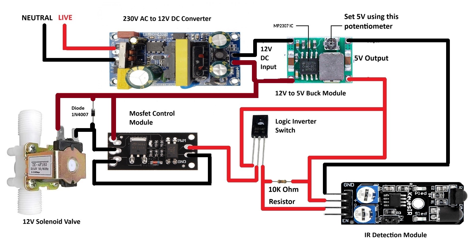
Circuit Diagram
Project Media
Click Here:
How It Works
The automatic water tap works based on the principle of Infrared (IR) detection. Here’s a concise theory of its operation:
- IR Sensor Module: The IR sensor emits infrared light. When an object comes within the sensor’s range, the emitted light reflects back to the sensor.
- Signal Processing: The sensor detects the reflected IR light and sends a signal to the connected circuit.
- MOSFET Control: The received signal is used to activate a MOSFET. It acts as a switch to control the solenoid valve.
- Solenoid Valve Operation: When the MOSFET is activated, it allows current to flow through the solenoid valve, opening it and letting water flow.
- Water Flow: The water flows as long as the object is detected by the IR sensor. Once the object is removed, the sensor stops detecting the reflection, and the solenoid valve closes, stopping the water flow.
Step-by-Step Guide
Prepare the enclosure:
- Drill 2 holes into the plastic enclosure, to be able to mount it to a wall.
- Drill additional holes to mount the components, you can use zip ties, or screw + clamps.
- Drill required holes to pass the incoming and outgoing wires.
Circuit Connections:
- Connect the components, according to the wiring diagram shown above.
- Do make sure to use heat shrink tubing, to avoid short circuit.
Connect the Solenoid Valve:
- Connect the solenoid valve wires, to its terminals.
- Connect the solenoid valve, with one end to the water tap inlet, and other end to the source.
- Keep in mind, the solenoid valve direction.
- If connected in reverse, the solenoid valve will either flow continuously, or won’t work at all.
Tap Connections:
- Attach a layer strip of insulation tape to the back of the sensor module PCB.
- Attach a double sided tape on top of the insulation tape, and press it firmly.
- Position the sensor, and stick it underside of the tap.
- Align the transmitter and receiver LEDs, so as to properly set the control area.
- attach a layer of insulation tape around the sensor pcb and tap. As shown in the video.
First Time Power-Up:
- After properly checking the connections, turn on the power to the circuit.
Calibrate the Sensor:
- Adjust the sensor position, angle, to have the desired control position.
Test the Operation:
- Place your hand in front of the tap. The sensor should detect your hand and open the solenoid valve, allowing water to flow.
- Remove your hand to stop the water flow.
Conclusion
This IR sensor-based automatic water tap project is an excellent way to enhance hygiene and convenience in both home and public restrooms. By automating the water flow, you can minimize water wastage and prevent the spread of germs through touch. Being cost effective, and easy to build, anyone interested, can make it.