4 minutes
Revision
Fundamentals of Electronics and Components
1: Introduction to Electronics
Description:
- Electronics involves the study and application of electrical components to control the flow of electricity.
- Fundamental concepts include voltage (V), current (I), and resistance (R), governed by Ohm’s Law: ( V = IR ).
- Statement: The voltage across a conductor is directly proportional to the current flowing thru it, and inverse the resistance of the conductor itself.
Key Concepts:
- Voltage: The potential difference driving current in a circuit.
- Current: The flow of electric charge.
- Resistance: Opposition to current flow.
Questions:
- What is Ohm’s Law, and how is it used in basic circuit analysis?
- What is the difference between series and parallel circuits in terms of current and voltage? Ans: In parallel circuit, voltage across all components is same, but current is different. In Series circuit, voltage across all the components is different, but current is same.
- Explain the role of a breadboard in circuit design and testing.
- Why does total resistance decrease in parallel circuits?
2: Understanding Components
Description:
- Electronic circuits consist of resistors, capacitors, diodes, and other fundamental components.
- Each component has a specific role: resistors limit current, capacitors store charge, and diodes allow current flow in one direction.
- Multimeters are essential for testing these components’ values and verifying their functionality.
Key Concepts:
- Resistor: Controls the flow of current.
- Capacitor: Stores energy in an electric field.
- Diode: Acts as a one-way valve for current.
Questions:
- How do you use a multimeter to measure resistance, capacitance, and diode functionality?
- Describe the significance of resistors in limiting current in circuits.
- What is diode Forward bias and reverse bias?
- What will happen if positive is connected to diode negative, and vice versa?
3: Transistors and Diodes
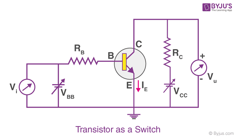
Description:
- Transistors: Semiconductors used for switching and amplification in circuits.
- Diodes: Used in rectifier circuits to convert AC to DC power.
- Practical applications include building switching circuits and simple rectifiers.
Key Concepts:![]()
- NPN and PNP Transistors: Types of bipolar junction transistors (BJTs).
- Rectifier Circuits: Convert AC power into pulsating DC.
- Switching Circuits: Enable or disable parts of a circuit based on input signals.
Questions:
- What is the difference between an NPN and a PNP transistor?
- How does a diode function in a rectifier circuit?
- Explain the concept of transistor amplification.
- How to use transistor as a switch?
4: Capacitors and Inductors
Description:
- Capacitors and inductors are passive components essential for filtering and timing applications.
- Capacitors block DC while passing AC, while inductors do the opposite.
- Practical tasks involve building RC (resistor-capacitor) and LC (inductor-capacitor) circuits to analyze their effects.
Key Concepts:
- RC Circuits: Used for filtering and timing applications.
- LC Circuits: Produce oscillations in resonant circuits.
- Filtering: Removing unwanted frequencies from signals.
Questions:
- What is the role of capacitors in filtering applications?
- How do RC circuits create time delays in circuits?
- Explain how inductors behave differently in DC and AC circuits.
- What is resonance in an LC circuit, and where is it applied?
5: Potentiometers and Variable Components

Description:
- Potentiometers: Variable resistors used to control voltage or current.
- Common applications include use in voltage divider circuits and adjustable resistance in devices like volume controls.
- Practical work focuses on adjusting circuit parameters by changing resistance.
Key Concepts:
- Voltage Divider: A circuit that divides input voltage into smaller parts.
- Adjustable Resistance: Adjusts current or voltage levels.
Questions:
- How does a potentiometer function in a voltage divider circuit?
- What are the practical uses of variable resistors in electronics?
- Explain the impact of increasing the resistance in a potentiometer on circuit behavior.
- How does a potentiometer differ from a rheostat?
6: Introduction to Integrated Circuits (ICs)
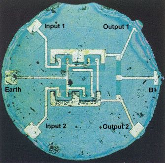
Description:
- Integrated circuits (ICs) are compact packages containing multiple electronic components such as transistors, resistors, and capacitors.
- Example: 555 timer IC used in generating signals like pulses and oscillations.
- Practical applications include using ICs for blinkers, tone generators, and other basic tasks.
Key Concepts:
- 555 Timer IC: A versatile chip used for timing, pulse generation, and oscillation.
- Oscillation Circuits: Generate periodic signals.
- Signal Generation: Producing waveforms like square waves.
Questions:
- What are the primary functions of the 555 timer IC in electronics?
- Describe the internal structure of an integrated circuit.
- How are ICs advantageous compared to discrete component circuits?
- Explain how a 555 timer is used to create a square wave oscillator.
7: MOSFETs (Metal Oxide Semiconductor Field Effect Transistor)
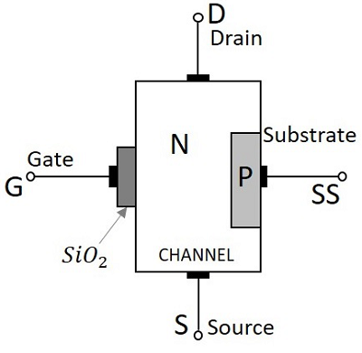
Description:
- MOSFETs: Semiconductors devices which are used to control high power devices.
- MOSFETs have different types, as shown in the image.
Key Concepts:
- Types: Types of MOSFETs (N channel , P channel)
- Kinds: Enhancement Mode, Depletion Mode
Questions:
- What is the difference between an N channel and P channel mosfet?
- How does a mosfet work as a switch?
- Explain mosfet selection.
- How to use mosfet in certain conditions.
End of Presentation
hehe, thank you guys
791 Words
2024-11-23 18:57